Monday, April 12, 2010

"Haste makes waste". This old adage often bears relevance to a project like this. Also the phrase, " Measure twice and cut once". More on that in a moment.
Before we tack the axle mounts in place there is one more thing to do. We do not want to tighten the bolts too snugly on the nylon pivot bearings because we want it to be free to flex up and down to compensate for bumps and dips in the road surface. In order to keep the bolt from turning we just need to tack on a small piece of 1/8" steel to the edge of the bolt to keep it from twisting as the swing arms pivot on them. We are only welding the small shim on three sides to the mount but not to the bolt itself. This way the bolt can be easily removed as necessary.
Now back to the haste and waste thing. Few of us have nothing more to do than to go to the garage and spend hours on end to work on a project. We have to steal an hour or two here and there. It is important to use the time wisely in order to make progress. I came out here tonight all ready to get this rear end tacked into place so we can be sure everything is falling into place as planned. As I said before I want to be through by the beginning of summer which I consider to be June first. That is not too many weeks away. So all I needed to do was weld the bolt stops on the mounts and proceed with the fit up. So why didn't someone notice that I was welding the stops on the wrong side of the mounts? It only took about 45 minutes to get all four stops firmly welded in place. Boy was I disappointed when I went to reassemble the swing arms. I was even thinking to myself the whole time, "Now don't get into a big rush here because you know what can happen". So once again I had to put the cutoff disc on the angle grinder and grind the stops off and grind the surface flat with the flap disc. I had to start all over again but there was no one to blame but myself. "Measure twice and cut once" is a good adage to apply to any construction project. I could have saved a lot of time and effort by simply checking the fit after the first stop was tacked on. Live and relearn.


Wednesday, April 7, 2010

I get tired of hearing and using the same old cliches. "It is what it is". This usually refers to a situation that cannot be changed or something unacceptable that we accept based on it's onerous nature. There is usually another side to the matter that may offer some equtiable solution if we are only willing to look. From now on my new cliche will be "It isn't what it isn't".
One of the problems you will run into when building a project is not having the right size material to make a part. It just isn't what it isn't. Often times you just have to use what you have at hand. For example the next part we need is a good solid pick up point to connect the rear trailing arms to. These mounts will need to be strong so I will be using some 1/4" thick angle iron. I need a piece of angle iron that has one leg about 1 1/2" long and the other leg about 4" long. All I have is 1 1/2" angle iron. But wait, I also have some 1/4" x 3" strip. If you have enough welding wire you can usually make just about anything work. Just grind a small bevel on the edges and slide the 2 pieces together. Be sure to tack both the front and back sides first so that it will not warp when finish welding. You want them to be nice and flat. This is where the angle grinder with a flap sanding disc really works well to grind the excess weld bead off. We will be using 1/2" bolts to connect the arms to the mounts.
Do you suppose that the welded spot may not be strong enough to stay together with the constant flexing of the rear swing arms? Well just to be sure we will install a couple of gussets to reinforce it. Gussets are nothing more than a piece of support to tie two pieces together so they cannot flex.


Gussets do not have to be anything fancy but they need to be flat in order to get the best weld possible. These strips of 3/16" thick should do the trick.


Magnets work well in holding the gussets in place while they are tacked on.


We need some nylon bushings for a bearing surface for the 1/2" bolts that the swing arms will pivot on.


The nylon bushings are sized so they fit snugly into the bearing housings. I will need to drill and tap some holes in the bearing housings for a grease fitting. You will notice that the housings are about 2" long while each of the bearings are only 3/4" long. This will leave a little gap in the housing for the grease. It is easy to forget little things like this once the project is nearly completed. It is a good idea to make a list of things to remember to do and keep it with your notes on the project for reference. I will do that right now.


Now we can bolt the swing arms onto the pick ups. Always use grade 5 nuts and bolts. Fine threads are preferable. Remember to put a metal back up washer on each side of the nylon bearings. It is best practice to use nylock nuts on the final assembly of any bolted component. A nylock nut is symply a nut with some nylon in the end that creates surface tension between the nut and the bolt thread in order to keep the nut from loosening up. In a somewhat crude bearing application like this you only want to tighten the nuts enough to make them snug so that the arm can move freely. You will notice that I have not used nylock nuts for the initial fit up. That is because regular nuts are much faster to assymble and disassymble. I hate to tell you this but we will have to take the entire cart apart for finish welding, sand blasting and painting. Nylock nuts cost more but they are well worth the money. Besides you can use the regular nuts over and over again anywhere they are needed.
Just as a side note, have you ever noticed that screws always rattle loose. Why can't they also rattle tight. Imagine you are riding along in your car and you say to your buddy , hey do you hear that sound in the dash? Yeah what is that? I think it's a tight screw. Just remember "it isn't what it isn't."


The next photo shows the basic components of the rear swing arms. We will now have to figure out exactly where to place it. Since I know where it is located from the CAD drawing it is just a matter of measuring to the centerline of the axle. What axle you might ask.

We will now use a piece of 1" tube to act as our axle in order to line everything up. The next photo illustrates the parts we are working with. The swing arm assymbly needs to be perpindicular to the center line of the cart. It is never a good thing to have the front end trying to go one way and the rear end go another. This can be observed in a vehicle with a bent frame. From behind it looks like the car is going down the road sideways. Also hard on the tires. You can't see it very well but in the center in between the swing arm mounts there is another set of Azusa bearings that are installed on the axle tube so that they can be perfectly lined with the outside bearings. The sprocket will be mounted to this set of bearings. We will be using a 1" axle with 1/4" keyway for the final drive system. You may ask why not just use the actual solid 1" axle we will eventually need to line it up. Shut up!! No this is a good question. We are not using a solid axle design so we can get by with a shorter length of axle for the completed drive system. Hopefully we will save a little money by purchasing a shorter lenth of solid axle. Besides, I have the 1" tube on hand and we will use it for other things as well.

Oh and by the way, don't forget to turn the frame over so you can install this assymbly on the underside of the cart. Of course you can do whatever you like. I usually do. In this next photo the frame is turned over and we will try to line it all up staight and perpindicular before tacking it on.


Sometimes I get so focused on one thing that I forget about the other parts of the project temporarily. But it is important to be sure that the rear end of the cart will work well with the front end that we spent a lot of time getting just right. There are a number of ways to set up the drive train on a rear wheel drive vehicle. I don't believe I have seen a front wheel drive go cart yet. You can go with a solid axle design, rear swing arms, trailing swing arms or possibly a combination. You may ask which drive train design is the best? I may ask which type of coffee maker is best? It depends on personal preference, cost, as well as performance considerations. Do we want to go fast or are we more concerned with torque and climbing ability. If you asked a kid, "what is the most important aspect of a go cart?", what do you think they would say? When I was a kid I would say what is an aspect. Most kids would say it's gotta be fast. I don't mean to disappoint you but speed is not one of the considerations for this project. This will be a rather slow beginner cart. I want it to ride very smoothly and have enough power to do a little climbing. If you ask me about the most important aspect of any vehicle I will say the brakes. Speed without brakes is kind of like neglecting to carry enough fuel in an air plane for the trip across the ocean just to increase the travel speed.
I have decided to go with an independent swing axle design. The first thing to do is determine how long the swing axles need to be. There are a number of design considerations for the drive system. They include,
1. Track width ( How wide between tires)
2. Drive sprocket size
3. Axel Bearings
4. Flexible Drive joints ( u-joints or cv joints)
5. Axel length.

This may sound a little involved but like anything else it is not that complicated if you break it down to one thing at a time. According to the CAD program there should be enough room for everything to fit and have an overall width of 52" from outside of wheels. The following photos show the swing axle design. This is the overall dimensions of the swing axle.

This next photo shows where the swing axle fits in the rear of the cart.
The next photo shows an item that has been used in lightweight power transfer applications ever since mankind switched from square to round wheels. It is called an Azusa Bearing Hanger kit. It consists of a bearing that floats inside of a flangete which is bolted to the hanger. The hanger is welded to the frame at the appropriate location and holds the axle in place so it can turn the back wheel. They come in all sorts of sizes and configurations to suit most any set up. Granted they are not designed for automotive drives but they work quite well for go carts. I am not sure if they are named after some inventor or if someone said Hey, lets named this something that is hard to pronounce. It is very simple and very functional. I love it!

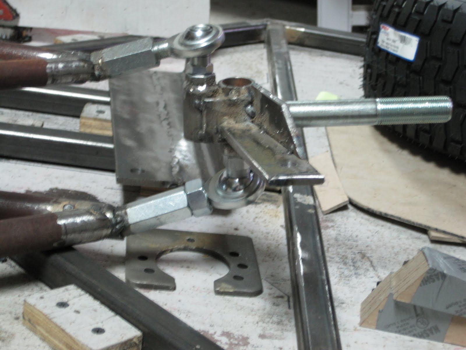
Earlier I spoke about fixturing as a way to produce accurate and consistent parts. The front suspension components were more or less free handed using chipboard patterns because any inaccuracy could be adjusted. The rear end will not be quite as forgiving so we will first build a fixture that will hold the parts in place until we can tack them together. Both swing arms will be exactly the same so building a fixture will ensure that both sides will be identical. The swing arms will consist of 3/4" tube for the arms, Azusa bearing hanger,1" Schedule 80 pipe for the pivot bearing housing and nylon pivot bearing inserts. Here is a picture of the fixture set up to hold everything in place.


The pieces are held in place using C clamps until everything is tacked together. The bearing hanger is welded to the outside and the 1" heavy wall pipe is welded to the other end. I got a little ahead and of myself and cut the center portion of the bearing holder before taking a picture of it. You will want to leave it whole until the arms are completely welded so that nothing will move out of place. You will find that parts tend to squirm around when you apply four or five thousand degrees F. of heat.


Monday, April 5, 2010

Now it is time to locate the pick up points on the nose section so we can assemble all of the components of the front suspension. It's got me in suspense because I want to see if it goes together like planned. Pick ups simply refer to the point at which the control arms are connected to the nose section. They are made of 1/8" thick steel with a 1/2" hole drilled at the appropriate spot to receive the 1/2" spherical joints that are screwed into the ends of the control arms. The easiest way to get the pickups to line up with the arms is to first locate one pick up and tack it in place. Now you can connect the arm to this first pick up and the second pick up will automatically be spaced for you. Just swing the arm over with the second set of pick ups to the side of the Nose and tack them on.
The next photo shows the control arms connected to the Nose and ready to receive the spindles.


The spindles are connected by simply screwing the upper arm into the 1/2" nut and the lower arm into the 5/8" nut on the spindle.


The next photo shows the spindles connected and ready for some wheels.


We not only need to connect the wheels to the spindles but they need to roll freely. Bearings are a wonderful yet simple way to make something rotate smoothly as well as acurately. Here is a picture of the front wheel hub and a set of bearings. It just so happens that it will fit a 3/4" bolt like the one we welded on the spindle. Wow! How did that happen? I guess I got lucky this time.


Now the main consideration when choosing a set of wheels is "what will look good". Not really. Yeah really. I see cars all over town with a set of wheels that are worth twice the value of the car. The rest of the car looks like a piecer but they are rolling in style. I chose a 16" diameter wheel x 6 1/2" width. I could explain what all the different sizing numbers for tires really means now that I was forced to learn them but that truly is some good bed time reading. You can find it on line if you are really interested. Maybe you already know. But the point is that most terms mean something specific in an industry and the way we use those terms may not be technically correct. For instance, the term wheel actually refers to the metal center portion which is bolted to the hub. Of course tire refers to the rubber portion. So don't ever go into a tire store and say you need a new set of wheels because that will really get them excited and all that glitters is not chrome.


Here is the wheel set I chose for the cart. How do I know that 16" will look good and work well for this project? I don't. But I saw a picture of another cart and it looked good on it. Later on we will be estimating the speed of this vehicle with a formula that includes the diameter of the wheel. More on that later.


Now that we have the wheels connected it is time to be sure they will move the way we intended before welding everything up. But first we need to see how the rack and pinion steering is going to fit.


Sunday, April 4, 2010

Here are the completed right and left upper control arms. The A arms are also called control arms because they control the movement of the front suspension. You will notice that the coupling nut end points away and upward at each end. Everything is the same for the left and right side except that it makes a difference which side you put the angled portion of the control arm. The next photo shows the patterns for the lower control arms. You say they look just like the upper arms. This is getting boring. I agree but they are slightly different. I have decided to make
both parts of the lower arms out of 1" tubing. I hope this will add some integrity to these supports. The next photo shows a 1/2" coupling nut prepared to weld on to the angled portion of the 1" tube. I hope I don't forget to grind the rust off of the pipe before welding. I think I forgot to mention that you also need to grind the plating off of the nuts at the point they will be welded so that it does not interfere with the weld.


This next photo shows the end that will connect to the spindle. I am using a 5/8" coupling nut on this end in hopes of providing a stronger support on the underside of the spindle. You will note that the plating has been ground off of the coupling nut so it will not contaminate the weld.

In this next photo you can see why it is important to weld the straight and angled part together in the correct orientation so that it will connect to the spindle at the correct angle. You may ask, If this is the lower arm shouldn't the rose joint be pointing upwards instead of downwards? You would be correct but since it is threaded you can turn it any direction you want and then tighten it down with the jam nut.


The next picture shows the lower control arms ready for action.


Thursday, April 1, 2010

Fixturing is an efficient way to accurately hold parts in place so they can be machined, milled, or welded. We will use some fixturing on the rear swing arm assemblies a little later but for now I will be using chipboard patterns as a guide in making the a arm links.


This is not a real accurate way to ensure that the right and left sides are exactly the same. But since there will be adjustment at each connecting point then being close should be close enough. The upper A arms are made using 3/4" tubing and the lower A arms will be made using a combination of 3/4" and 1" tubing. The next photo shows the 3/4" tubing with a 1/2" nut tack welded to one end. This nut will receive a 1/2" spherical joint that connects to the nose assembly. A spherical joint is a flexible connector that allows for limited movement. They are also referred to as Heim joints and Rose joints. I am using magnets to help hold the parts in position while being welded. The next picture shows a coupling nut welded to the other end. This must be angled in order to hold the spindle in the correct position. A coupling nut is just an extra long nut. It is needed here because the angle of the pipe would prevent the Rose joint from being screwed into the end. The next photo shows angled portion of the A arm with a Rose joint screwed in the end.
This Rose joint has male threads on each end. It will be screwed into the 1/2" nut that we welded on the spindle.


The next photo shows the angled portion of the A arm welded to the straight portion. It also has a coupling nut welded to the end. This completes the right upper A arm. The left Upper A arm is exactly the same as the right except that it is a mirror image of the right. You can use the same patterns but remember to be sure the pivot nut end points in the right direction. Did I remember? Thank goodness for angle grinders.


The next fab will determine just how well this little machine will handle on the road. Utilizing a fully adjustable front suspension requires a number of design considerations. For instance, where am I going to put the connecting points and how will they be constrained to move in the desired direction? How far will they be allowed to move? When it moves in the parallel plane will it move favorably in the horizontal plane? Without some means to model these opposing movements it is a matter of trial and error and most of the trial will be error. Allen Staniforth developed what he refers to as a string computer that utilizes card board and paper components scaled to size and constrained with brads and string in order to simulate movements of the front suspension in various configurations. I am sure this works well but I prefer to use a computer computer. This first photo shows a top view of the suspension. This will be a double A arm suspension so this shows the upper A arm. The bottom A arm would be located right below it. Why is it called an A arm? I wondered about this for a long time. It is because the arm is sort of shaped like an A. Can you guess why it is a double A arm suspension? The next photo is a view from the rear. It shows exactly where to place the A arms on the front nose section we just built and locates the direction of the wheel in the Y Plane. In two dimensional drawings we refer to side to side dimensions as the X Plain and the up and down directions as the Y plain.
You can't tell it very well from this next photo but it shows the position of the wheel in 2" of bump. For instance this shows the position that the wheel assumes when you run over a 2" high bump in the road. The idea is to keep as much of the tire in contact with road surface as possible so as to maintain control of the vehicle. This is also important when turning a corner because the chassis assumes a position similar to the forces exerted from a bump when cornering. The computer shows that we gain only one half of a degree of negative camber in 2" of bump. Is this a good thing? Is it good, better or best? I don't believe from my limited knowledge that there is a perfect suspension. Anything you gain in one area you lose in another. At least this will eliminate a lot of what is referred to as bump steer. If you have ever driven a vehicle with limited suspension you will recognize this phenomenon as the way the steering wheel jerks in you hands when you hit a bump. I want the smoothest ride possible for my girls. Besides you can easily turn that half of a degree of positive camber into a more desirable negative camber with the adjustment that this design affords.