Monday, August 30, 2010

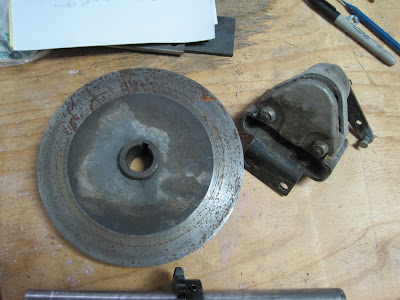
The rear sprocket finally arrived so we can continue with the drive train. I also bought a different sprocket mounting hub. You will notice that the sprocket is broken in two. Of course that is on purpose in order to make Assembly and removal easier. Sprockets wear over time and must be replaced. Having the sprocket so that it can bolt on in two pieces allows you to change the sprocket without having to disassemble the rear drive train. This is a racing sprocket so it is supposed to be made out of some pretty good aluminum. I guess we will see just how good it is. The two halves simply bolt onto the sprocket hub.

Now we can get a good idea of exactly where the drive sprocket and hydraulic motor need to be spaced. It looks like there will be plenty of room for everything.

Here is a view from the top.


Now that everything is clamped in place it can be marked for drilling the holes in the frame for the pillow block bearings.


You will notice that the pillow blocks have slotted holes that allow for some adjustment. This is a good thing because all of the components together may not line up exactly as planned and you do not want the jack shaft to be in a bind. You could actually use this slotted hole in conjunction with a drilled slot in the frame and acquire enough movement to tension the chain. That would be entirely acceptable except that you would need to build some adjusters. I prefer to keep it as simple as possible . Once the bearings are bolted in place you do not want any movement. So the question remains as to what method to use in order to tighten or loosen the chain. Let's get the holes drilled for the bearings and then look at a method for adjusting the chain.


I like to use a smaller drill bit to spot the correct location of a larger hole that needs to be drilled because it is easier to see if the drill bit is in the exact spot you want to drill.


Once the hole location is spotted and the piece is bolted securely in place then change out the smaller drill bit for the finish size bit and the hole can be drilled exactly where you want it.

You will notice in the next photo that the color of the frame is lighter and all of the rust has been removed. The sand blast cabinet was open so I threw it in and blasted it for a couple of minutes.

Now back to the chain adjustment. Since there are two bearings it would be necessary to move both bearings equally in order to adjust the chain tension. These bearings need to be in perfect alignment with each other and the hydraulic motor in order to move smoothly and minimize wear. I like the idea of bolting everything firmly in proper alignment and using an independent means for adjusting the chain. I was discussing this with my good friend and engineer Jim Chitwood of Chitwood Engineers. He suggested that I use a chain tensioner. WOW! That is a great idea. Jim once designed a water jet cutting machine that we built together. That could be the subject of another Blog. So I go to the Graingers catalog to find a chain tensioner. Whoa!! One hundred dollars and that doesn't even include the idler sprocket and shaft. So let's get back to reality here. A chain tensioner is nothing more than a simple way to put pressure on the chain in order to take up excessive slack. It consists of an arm with an idler sprocket attached that can be pushed against the chain and bolted into place. I had already fabricated a simple assembly for this purpose but it would not fit properly into the hole that I drilled as you can see in the next photo.

So forget that. All we need is a 3/4" nut welded onto the upright of the frame so that the tensioner can be bolted in place.

The tensioner consists of a piece of 3/8" thick steel that serves as an arm. Holes are drilled in both ends of the arm. One hole pivots on the 3/4" bolt that will tighten the arm at the correct tension of the chain. The other end is drilled for a 1/2" bolt that holds the idler sprocket in place.

So let's put the drive assembly back in place and see how the tensioner works. It is close but looks like it will work fine.

Saturday, August 21, 2010

The following page shows the calculations that I am using to determine the performance characteristics of the cart. I said earlier that I would like to incorporate moderate power and speed. Moderate can mean anything but in this case I just want a safe way to transport two young ladies across some possibly rough terrain. In general the performance of any vehicle is determined by a combination of gear ratio and horse power. I have picked out an arbitrary figure of 10 miles per hour as a relatively safe speed for a beginner go cart. I am trying to achieve this using single reduction gearing meaning basically that there are only two sprockets involved. I found a Gear Ratio MPH Formula on the web site of Electric Motorsports which automatically figures the speed produced by feeding in the number of teeth on the sprockets, RPM of the motor and the circumference of the tire. As you can see the design calls for a 15 tooth drive sprocket ( connected to the hydraulic motor), 40 tooth driven sprocket ( connected to the rear drive axle), 600 RPM motor speed, and 50 inch circumference of the tires ( 16 inches x Pi). This formula should produce between 10 and 11 miles per hour. Now I admit that there are a lot of assumptions I am making here and this may not work at all like I have planned. But at least I have a plan based on some known premises. I am concerned about the following list of things:
1. Will the hydraulic motor turn at least 600 RPM?
2. Will the hydraulic motor be strong enough?
3. Will the 5 horse power engine provide enough torque to power the hydraulic pump?
4. Will the 2 stage pump work the way I think it will?

I want to give a little reasoning on using a two stage pump. Basically what this means is that the pump will supply a certain volume of fluid according to the load that is required. For instance in a log splitter a two stage pump is very useful because it supplies a lot of fluid when there is very little pressure required, for instance when retracting after splitting a log or taking up slack before splitting a log. It supplies a lot of fluid in the first stage and less fluid in the second stage. When the pump is in the first stage the hydraulic ram moves quickly as it approaches the log. But as the log is pushed into the wedge to begin the splitting process, the pump senses the resistance and automatically switches into the second stage where the supply of fluid is delivered at a slower pace but with more force. Now this is where I am not sure if this will work the way I want it to in the go cart. My hope is that it will perhaps work in reverse of the way it does on the log splitter. The greater load will be needed in order to get the go cart moving therefore utilising the second stage on start up. Kind of like the reverse of the way a log splitter works. But as the cart begins to roll my hope is that it will switch into the first stage and provide the speed required for cruising. If you try to drive it up a steep incline then hopefully it will switch into the second stage and supply the power needed to make it up the hill albeit at a slower speed.
You can begin to see the many unknowns that exist in this design. I wish that I felt more assured in taking this route but this is what the application of knowledge is all about. We should grow from failure as well as success.


As a side note, I do not remove my wedding ring when working in the shop. This can be dangerous for a mechanic or equipment repair technician because of the possibility of something catching on it and possibly ripping your finger off. But we all take calculated risks in everything we do whether it is riding in a car or walking down the street. I choose to leave my ring on and work with gloves whenever possible. Last night I wanted to make one last quick little weld but did not bother to put my gloves on. A piece of slag is now firmly embedded on the surface of my ring. I am sure it will come off easily with a file but wanted to alert you to the possible hazards of wearing any kind of jewelry when fabricating metal. I never wear my tongue pendant or nose ring while working. ( that is a joke). OK. We need to get on with the drive train. Now that the components of the drive train have been located properly we will need a way to hold them firmly in place. We want to be sure that these components are also kept in perfect alignment. Some 1/4" thick angle iron will work nicely. The hydraulic motor needs to be held in place and the one inch pillow block bearings need to be bolted down firmly. I like the idea of building this as a separate frame unit that can be welded into place. The bearings will be bolted to the frame for easy removal. You will notice that I am not allowing provision for tensioning the drive chain. Heck, don't be so pushy! I don't even know the exact location of the frame unit yet. You know me by now. I don't plan for anything.


Here is the basic frame waiting to be drilled for placement of the pillow block bearings. I will have to wait until the rear sprocket comes in before I can drill the mounting holes and put the Assembly in place.


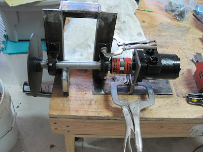
Here is the Assembly with the motor, coupling, drive shaft, bearings and brake disc in proper placement.


Sunday, August 15, 2010

We have been on an Alaskan cruise for the last two weeks. This was our first cruise and we had a great time. I have always thought of Alaska as a wild exotic far away place, a frontier at the edge of no where. It is! We flew in a plane over Mount Mc Kinnley, went whale watching, flew in a bush plane to watch the bears dine on the Salmon run, road a boat on a glacial fed river to view Eagles and Moose. We saw glaciers and Sea Lions and snow capped mountain ranges. But one of the things that I found most interesting is panning for gold. We visited a gold mining operation that was also used as a tourist attraction designed to familiarise you with gold mining. After a short train ride through the mine there was a demonstration on sluice mining method after which we were each given a small bag of pay dirt to try and remove the gold from the dirt and rock by means of panning. Gold is at least 10 times heavier than other rock and minerals so the idea is to wash the lighter rock and dirt out of the pan and leave only the gold to be harvested. I got most of the lighter minerals and rock out of my pan and then let one of the experienced assistants finish the final panning. Here is what gold looks like after panning. These are flakes of gold but no nuggets. But gold is gold. I now understand what "Gold Fever" means. I am ready to stake a claim somewhere.


It has been a hot summer so far and the heat makes it difficult to work in the garage with my small fan. Twenty years ago that would not have a lot of effect on me. But this is not twenty years ago so I have learned to pace myself.

We have come to the point in this project where we must decide exactly how to transfer power from a gasoline motor to the drive sprockets and chain. There are many options to be considered and I have thought about them all or at least as many of them as I know about. The main ones are as follows:


1. Friction clutch with chain drive.


2. Batteries with electric motor drive.

3. Hydraulic drive.


Each method has its' positive as well as negative features. We could have a really long dialog about all of the different methods and how to achieve them but I am not an expert so I will list the criteria that I am trying to achieve in this project and some of the reasons for my choice.

I would like to achieve the following:


1. Moderate speed and power. ( what does that mean?)
2. Efficient speed control.
3. Smooth power transfer from engine to drive train.
4. Easy and efficient reverse.
5. Good brakes.


Using a friction clutch that attaches to the engine shaft would be the most simple way to go but then there would be no simple way to incorporate a reverse of course unless you want to buy an expensive reversing gear box. If you just want something that goes forward and goes fast then the friction clutch or torque converter would be the way to go. But I want this cart to travel at a safe speed for beginners and have a way for them to back up without having to get out and push the cart backwards. This could be achieved by using a transaxle and transmission from an old riding lawn mower but I want a little better performance than that would supply. Besides we are a little past the stage of easily incorporating a transaxle into our design. I like the idea of an automatic transmission. Hydrostatic hydraulic drive for tractors and lawn mowers is an efficient way of eliminating gears and special clutches from the drive system. Basically you just push the accelerator pedal forward to go forward and push it backwards to go in reverse. I have decided to use my limited knowledge of hydraulics to build a drive train from readily available common components in order to achieve the goals listed above. I have tried to research this method on the Internet but cannot find very much where this method has been used for a go cart. Most of the time that means it probably is not a good method. But I like a challenge. I suppose only time will tell if it works well or not.


The first thing that needs to be determined is what performance criteria you are looking for. Then you must choose the components that will both meet those performance requirements as well as work in a balanced proportion with each other. The following rough sketch is the basic set up for our system. I will probably need to make changes as the actual fit up of parts continues.


The following photo shows the individual drive components.


The following is a disc brake that will be incorporated into this cart. It came off of a prior project that I plan to rebuild in the future using the drive axle from the old golf cart I disassembled.


The following photo is the hydraulic motor I have chosen. It is described as a Dynamic low speed, high torque hydraulic motor. 11.85 GPM( gallons per Minuit) 2050 PSI. It has the following performance and dimensional specs:


Fully reversible, 4 bolt mount,1 in. x 1 3/4" long shaft has 1/4" key way, 1/2" NPTF( national pipe thread female) ports. Orbiting gerotor principle. 880 maximum RPM. Maximum torque of 885 inch pounds. Maximum flow of 11.85 GPM. It weighs 13 pounds. It is available at Northern Tool under item# 1040 and costs $180.00.

As you can see it is an expensive item. But it does take the place of friction clutches and other secondary gear reduction. For anyone who may be interested I will give you the calculations for the hydraulic drive system later on.
I plan to use a good Honda gasoline motor that will start every time you pull the starter rope. I would like to have an eclectic start but I figure that the girls will only ride under close supervision so there will always be an adult to start the engine. When they get older they will be able to start it themselves. The plan is based upon the power of a 5 horse power engine that has a maximum RPM of 3600. I am concerned that 5 h.p. may be a little underpowered so I will have to do a little more thinking on this.


The following is what is referred to as a Love Joy coupling. It is a flexible joint used to connect the hydraulic motor to the jack shaft that turns the drive sprocket. The white part is a hard rubber cushion that absorbs shock from the torquing of the motor input shaft. You cannot tell it from this picture but everything has a 1/4" key way to hold it stationary on the shaft.


Here is the 1" jack shaft or drive shaft that will turn the drive sprocket and also the brake disc. In this picture I did not have it turned so that you could see the key way but it has a 1/4" key way that runs the entire length of the shaft.


We will use two one inch pillow blocks like this one to support the shaft.


The following shot shows the components as they will be oriented in their final orientation. Yeah my writing skills are really on it today. The brake disc on the end of course will be turned sideways so it can slide onto the shaft.


The first thing we need to do is build a mounting bracket for the hydraulic motor. As you can see the motor is designed to be mounted using four 3/8" bolts. The shaft is one inch diameter but there is a raised step on the outside that measures one and three quarters diameter. I do not have a 1 3/4" drill bit and they are expensive. Besides it probably would not fit in the chuck of the drill press. So what do we do.


Thank goodness for the bi metal hole saw. I am amazed at how easily it can cut through a 1/4" thick piece of plate steel.
You will need to find a way to bolt the mounting plate to the press while drilling the hole. I am using machine blocks with clamp straps because I have them available in my shop at work. But you can use large C clamps or vice grips to hold the piece in place while it is drilled. Remember to use WD 40 or some kind of lubricant to reduce heat and friction.

The hole saw makes a surprisingly smooth cut. Of course it was brand new also.
Either I was a little off on the center hole or on the mounting holes. I will need to use a round file to wallow the holes a little to make them fit. I was just guessing at how long to make the mount. I have not decided whether this will be welded in place or bolted on. We can always weld on another piece such as a piece of angle iron if needed. We now have a mounting plate for the hydraulic motor.