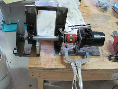
1. Will the hydraulic motor turn at least 600 RPM?
2. Will the hydraulic motor be strong enough?
3. Will the 5 horse power engine provide enough torque to power the hydraulic pump?
4. Will the 2 stage pump work the way I think it will?
I want to give a little reasoning on using a two stage pump. Basically what this means is that the pump will supply a certain volume of fluid according to the load that is required. For instance in a log splitter a two stage pump is very useful because it supplies a lot of fluid when there is very little pressure required, for instance when retracting after splitting a log or taking up slack before splitting a log. It supplies a lot of fluid in the first stage and less fluid in the second stage. When the pump is in the first stage the hydraulic ram moves quickly as it approaches the log. But as the log is pushed into the wedge to begin the splitting process, the pump senses the resistance and automatically switches into the second stage where the supply of fluid is delivered at a slower pace but with more force. Now this is where I am not sure if this will work the way I want it to in the go cart. My hope is that it will perhaps work in reverse of the way it does on the log splitter. The greater load will be needed in order to get the go cart moving therefore utilising the second stage on start up. Kind of like the reverse of the way a log splitter works. But as the cart begins to roll my hope is that it will switch into the first stage and provide the speed required for cruising. If you try to drive it up a steep incline then hopefully it will switch into the second stage and supply the power needed to make it up the hill albeit at a slower speed.
You can begin to see the many unknowns that exist in this design. I wish that I felt more assured in taking this route but this is what the application of knowledge is all about. We should grow from failure as well as success.

As a side note, I do not remove my wedding ring when working in the shop. This can be dangerous for a mechanic or equipment repair technician because of the possibility of something catching on it and possibly ripping your finger off. But we all take calculated risks in everything we do whether it is riding in a car or walking down the street. I choose to leave my ring on and work with gloves whenever possible. Last night I wanted to make one last quick little weld but did not bother to put my gloves on. A piece of slag is now firmly embedded on the surface of my ring. I am sure it will come off easily with a file but wanted to alert you to the possible hazards of wearing any kind of jewelry when fabricating metal. I never wear my tongue pendant or nose ring while working. ( that is a joke).
 OK. We need to get on with the drive train. Now that the components of the drive train have been located properly we will need a way to hold them firmly in place. We want to be sure that these components are also kept in perfect alignment. Some 1/4" thick angle iron will work nicely. The hydraulic motor needs to be held in place and the one inch pillow block bearings need to be bolted down firmly. I like the idea of building this as a separate frame unit that can be welded into place. The bearings will be bolted to the frame for easy removal. You will notice that I am not allowing provision for tensioning the drive chain. Heck, don't be so pushy! I don't even know the exact location of the frame unit yet. You know me by now. I don't plan for anything.


No comments:
Post a Comment