I hope these short videos will illustrate how the hydraulic drive system works. So far it seems to work the way I had envisioned but of course the real proof will be in how well it rides with the kids on board. There seems to be some binding when I put it in reverse. I think it has something to do with the chain tensioner being too loose. So what is next? If you said tighten all the bolts and go for a test ride then I don't think that would be a good idea because everything is only tack welded so far. Now we have to take everything apart and finish weld the entire frame and each individual component. Next it will be sand blasted and then painted. I guess I better go get some more welding wire. The pet monkeys won't be much help because I have not had a chance to teach them how to use the MIG welder. A monkey using a mig welder, that would be silly. They only know how to use a stick welder.
Tuesday, November 23, 2010
Monday, November 22, 2010
When I tried to bolt the wheels to the axles I discovered that the threads on the axle were flat and also had been painted right along with the rest of the axle. So I had to get a threading die to clean up the threads before I could finish assembling the rear drive train.

I also had to add a tab to hold the return spring for the brake pedal. There are so many little things to be done that I am not sure I can find enough time before Christmas to get this cart finished.

I finally got all of the hydraulic hoses and fittings connected. Here is a short explanation of how it should work.
Some of the hoses are too short but they will have to do for the test run. This photo shows the return line running from the filter to the tank.

Here are the 2 ports of the motor connected to the control valve.

Here is a side view that shows the return line from the control valve to the filter.

Now that everything is connected it is time to see if a hydraulic gocart really works.
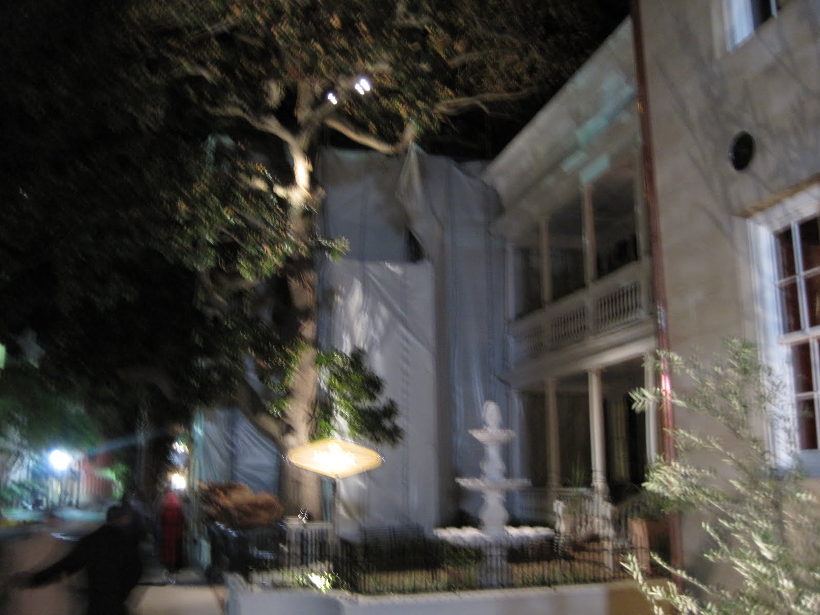
A couple of weeks ago we were in Charleston South Carolina for my neices wedding. This is a very interesting town rich with history dating back to the revolutionary times. We decided to go on a walking ghost tour at night and learn a little more about the cryptic history of the town. I have no explanation for this mysterious video that just showed up on my I phone.

I also had to add a tab to hold the return spring for the brake pedal. There are so many little things to be done that I am not sure I can find enough time before Christmas to get this cart finished.

I finally got all of the hydraulic hoses and fittings connected. Here is a short explanation of how it should work.
1. The hydraulic pump is connected to the engine.
2. The hydraulic pump receives fluid from the hydraulic tank.
3. The pump sends fluid to the control valve.
4. While the control valve is in neutral it simply allows the fluid to pass through and return to the tank.
5. When the pedal is depressed forward it sends fluid to the hydraulic motor and turns the wheels in forward direction.
6. When the pedal is depressed backwards it reverses the direction of the flow and activates the reverse direction.
7. The fluid is returned to the tank through a filter which strains out any contaminants from the hydraulic oil before recycling through the circuit.
In the following photo you can see the hose connecting the hydraulic pump to the control valve. The control valve is below the pump.
In the following photo you can see the hose connecting the hydraulic pump to the control valve. The control valve is below the pump.

Some of the hoses are too short but they will have to do for the test run. This photo shows the return line running from the filter to the tank.

Here are the 2 ports of the motor connected to the control valve.

Here is a side view that shows the return line from the control valve to the filter.

Now that everything is connected it is time to see if a hydraulic gocart really works.
A couple of weeks ago we were in Charleston South Carolina for my neices wedding. This is a very interesting town rich with history dating back to the revolutionary times. We decided to go on a walking ghost tour at night and learn a little more about the cryptic history of the town. I have no explanation for this mysterious video that just showed up on my I phone.
Tuesday, November 2, 2010
I had to make a slight modification to the chain tensioner so that it would have a little more adjustment. The 5/8" bolt was interfering with the adjustment so I had to cut it off and weld it to the idler arm as opposed to bolting it on with a nut. It needs to be flat on this side so it can be pushed farther back into the frame. This will make it difficult to remove the idler sprocket if necessary but it was the quickest and easiest fix I could think of at the time. And speaking of time, this project is getting so far behind schedule that I may need to build a real car for the girls if I don't pick up this pace. But it is not like I have been sitting around eating do nuts and watching TV. I just spent the last 3 weekends replacing soffit that had rotted on the garage. I thought it would entail a couple of feet but turned into about 20 ft. that needed to be replaced.  Now we are getting to the fun part of the hydraulics. The hydraulic motor, pump, control valve, and tank all have to be connected with hoses and fittings. The following photo shows some of the components. Starting at the top we have a piece of 3/4" low pressure return hose. Next is a row of 3/4" street elbos, followed by 1/2" street elbos, then 1/2" male by -8 JIC 90 degree elbos, 1/2" x -8 straight, 3/4" to 1/2" bushings and the bottom row is 3/4" male hose barbs that fit into the 3/4" hose. This will get us started.
 First off we will screw the strainer into the hydraulic tank. I am using teflon thread sealant tape in these connections. Some say that you should not use teflon tape upstream of the pump and valves in a hydraulic application because just a small piece of teflon tape can clog a hydraulic component. I know this is true from personal experience. However I am going to be extra careful not to let any extra tape get into the joint and it should be fine. Here a gain the Captain of the Titanic probably made a similar statement.

This is the supply end of the tank that will feed directly into the pump. It is all going to be a tight fit.
 The hydraulic tank is now connected to the pump. I am going to need to enlarge the mounting holes for the tank in order to move it slightly so this can all fit. The piece of hose on the left is not connected to anything yet and I am just trying to get an idea where to mount the filter which will be in the return line. You will notice that I have installed two fittings on top of the control valve. They are pointing back toward the hydraulic motor so I can determine the length for the connecting hoses.

Here is a shot from the hydraulic motor back toward the control valve.

 Now we are getting to the fun part of the hydraulics. The hydraulic motor, pump, control valve, and tank all have to be connected with hoses and fittings. The following photo shows some of the components. Starting at the top we have a piece of 3/4" low pressure return hose. Next is a row of 3/4" street elbos, followed by 1/2" street elbos, then 1/2" male by -8 JIC 90 degree elbos, 1/2" x -8 straight, 3/4" to 1/2" bushings and the bottom row is 3/4" male hose barbs that fit into the 3/4" hose. This will get us started.
 First off we will screw the strainer into the hydraulic tank. I am using teflon thread sealant tape in these connections. Some say that you should not use teflon tape upstream of the pump and valves in a hydraulic application because just a small piece of teflon tape can clog a hydraulic component. I know this is true from personal experience. However I am going to be extra careful not to let any extra tape get into the joint and it should be fine. Here a gain the Captain of the Titanic probably made a similar statement.
This is the supply end of the tank that will feed directly into the pump. It is all going to be a tight fit.
 The hydraulic tank is now connected to the pump. I am going to need to enlarge the mounting holes for the tank in order to move it slightly so this can all fit. The piece of hose on the left is not connected to anything yet and I am just trying to get an idea where to mount the filter which will be in the return line. You will notice that I have installed two fittings on top of the control valve. They are pointing back toward the hydraulic motor so I can determine the length for the connecting hoses.
Here is a shot from the hydraulic motor back toward the control valve.

Thursday, October 14, 2010
The brake linkage is finally worked out and now it can be assembled. Here is the rear control rod receiving the 5/16" bolts to connect the clevis.

Here is a shot of the rear linkage of the brake control rod.

Last week we Brenda and I took some time off to go to our cabin on Lake Tenkiller in Oklahoma. The weather was perfect with 40's in the morning and daytime highs in the 70's. Here is a view from the front porch facing west.
 If you have ever watched the movie "Where the Red Fern Grows" then you may recognize this next photo as the old country store in the movie. It is still in the family that ran it as a store in the early 1900's and is now used as a restaurant on weekends. Uncle Roy and aunt Nancy have eaten here and say it is good old fashioned home cooking. We went for a drive with Uncle Roy and aunt Nancy Brackett along with my mom and dad. Uncle Roy and Peary grew up in this area and they can take you so far back in the woods that they can't even truck in daylight.

This is a camping spot not far from the store. I am not sure but this may be the spot where they filmed the coon dog hunting contest. I bet there are still plenty of coons in these woods. I don't think Raccoons will ever be on the endangered specie list. Perhaps the overabundance list.

Here is Roy and Nancy. This once again shows my great ability as a photographer. (Sorry about that aunt Nancy).

Here is Mom and Dad.

The siding on our cabin is a log siding that makes it look like a real log cabin. It does look good but does require a lot of care. I noticed a board that was beginning to rot under the window sill on the North side and had planned to replace it right quick while we were here. Well, it didn't turn out to be as quick and easy as I thought. Water had gotten behind the boards and before I knew it we were into about a dozen boards. I checked the west side and found several more that needed replacement.


Uncle Roy came over and caulked the windows real well so we shouldn't have anymore problems with this. Thank you Roy! Brenda did all of the staining. Thank you Brenda!

Give it about a year of weathering and you will not even be able to tell the difference in the new and old siding.

I really have been continuing to work on the go cart project. There are so many tedious little things to finish. I had to add some bracing on the floor in order to mount the hydraulic tank under the seat. The side rails are at an angle so here is a place to use the angle measurin thang.

It is a bit crude but effective.
Here is the engine mounting frame tacked in place, drilled and ready to accept the engine.

One more brace to support the hydraulic tank mount.
 We will need a return spring on the brake linkage.

Here is a shot of the finished rear brake linkage.

It just takes time to drill all of the mounting holes for various components. I wanted to be able to remove the roll cage so it needs some good strong bolts to bolt it down. I have chosen to use 7/16" grade 8 bolts.

Here is the engine with the pump mounted.

 If you have ever watched the movie "Where the Red Fern Grows" then you may recognize this next photo as the old country store in the movie. It is still in the family that ran it as a store in the early 1900's and is now used as a restaurant on weekends. Uncle Roy and aunt Nancy have eaten here and say it is good old fashioned home cooking. We went for a drive with Uncle Roy and aunt Nancy Brackett along with my mom and dad. Uncle Roy and Peary grew up in this area and they can take you so far back in the woods that they can't even truck in daylight.
This is a camping spot not far from the store. I am not sure but this may be the spot where they filmed the coon dog hunting contest. I bet there are still plenty of coons in these woods. I don't think Raccoons will ever be on the endangered specie list. Perhaps the overabundance list.

Here is Roy and Nancy. This once again shows my great ability as a photographer. (Sorry about that aunt Nancy).

Here is Mom and Dad.

The siding on our cabin is a log siding that makes it look like a real log cabin. It does look good but does require a lot of care. I noticed a board that was beginning to rot under the window sill on the North side and had planned to replace it right quick while we were here. Well, it didn't turn out to be as quick and easy as I thought. Water had gotten behind the boards and before I knew it we were into about a dozen boards. I checked the west side and found several more that needed replacement.


Uncle Roy came over and caulked the windows real well so we shouldn't have anymore problems with this. Thank you Roy! Brenda did all of the staining. Thank you Brenda!

Give it about a year of weathering and you will not even be able to tell the difference in the new and old siding.

I really have been continuing to work on the go cart project. There are so many tedious little things to finish. I had to add some bracing on the floor in order to mount the hydraulic tank under the seat. The side rails are at an angle so here is a place to use the angle measurin thang.

It is a bit crude but effective.

Here is the engine mounting frame tacked in place, drilled and ready to accept the engine.

One more brace to support the hydraulic tank mount.
 We will need a return spring on the brake linkage.
Here is a shot of the finished rear brake linkage.

It just takes time to drill all of the mounting holes for various components. I wanted to be able to remove the roll cage so it needs some good strong bolts to bolt it down. I have chosen to use 7/16" grade 8 bolts.

Here is the engine with the pump mounted.

Monday, September 27, 2010
This morning when I turned on the water in the shower somehow I lost my balance for a second and knocked the heel of my foot against the bottom of the shower door. There is a plastic strip that holds the seal in place on the bottom of the door and it has a sharp corner on it. So first thing "I cut my heel and had to cruise on back home". ( Name that tune) I find it interesting how so many little mishaps seem to be always waiting for just the right time to occur. I was using one of the magnets to hold the roll bar in place temporarily until it could be positioned for tacking into place. Those magnets are made for sticking to flat surfaces but not to round bars. So you can see the magnet down there that let go from its' perch on the top of the roll bar. And just where did it choose to land? Yes, right on top of the gas tank. And did it choose to land flat? No way! It landed square on the corner in order to make the deepest dent possible. You can see the proud smile on that magnets face. 
 I have been fighting with the roll bar trying to get it even as viewed from the side and the front. I now realize that the following photo should have been shot using the zoom. I was trying to show what the roll bars look like from the front view. They are not perfect but they are as close as I am going to get them.

Side view of roll bars.

Here is a quick list of the fabs that need to be finished.


The brake caliper proved to be a tight fit but I think it will work just fine. I will mention at this time that the brake disc is not mounted in the best place possible due to room constraints. It is mounted on the primary drive sprocket axle. The better location would be the secondary driven sprocket axle. Why would that be a better choice? If you said because now the braking depends on the integrity of the chain, you would be correct. In other words since the braking power, just like the driving power, is transferred to the rear sprocket via the chain, the braking power as well as the driving power will be lost in the event of a broken chain. I thought long and hard about this but this brings up another issue. There is not quite as much ground clearance as I would like to have on the rear sprocket because it actually protrudes from the bottom of the frame an inch or so. I will try to build a skid plate to help protect it. The brake disc has a larger diameter than the sprocket so it would protrude even farther making it vulnerable to getting bent on a rock or something solid on the terrain. Bent brake discs don't work either. You may suggest that the brake disc could be mounted on one of the outboard drive axles. That could also work but then it would be necessary to build the caliper mount as part of the swing axle so it could float as the axle travels up and down. We could go on and on but a decision has to be made. I have opted to keep the disc up out of harms way and trust the integrity of the chain. After all it's not like the cart may go sailing through an intersection if the chain fails.
A piece of 1/8" angle iron will be adequate for the caliper mount.

 The caliper is designed to float back and forth on the mount as needed to line up with the disc. The lever will be connected to the control rod.
 In the following photo you can see how the channel in the mount fits into the slot on the caliper. Now the control rod can be attached.


 I have been fighting with the roll bar trying to get it even as viewed from the side and the front. I now realize that the following photo should have been shot using the zoom. I was trying to show what the roll bars look like from the front view. They are not perfect but they are as close as I am going to get them.
Side view of roll bars.

Here is a quick list of the fabs that need to be finished.
1. Roll bars
2. Brake caliper
3. Break linkage.
4. Engine mount.
5. Finish keying axles.
6. Install hydraulic tank.
7. Hose and piping
8. Body mouldings.
9. Floor board and dash.
I know that sounds like a lot but fortunately I am already in various stages of working on most of it. I decided to mount the engine on some 1/4" angle iron. We will not need to allow for any kind of adjustment in the engine mount because it is not attached to any drive train as in a regular friction clutch application. There just needs to be adequate room for the hydraulic pump to be mounted to the engine. It will be a tight fit in places but so far it appears that everything can be located without any major changes of anything that has already been mounted. Here is the engine mount ready to be drilled with the engine mounting holes.


The brake caliper proved to be a tight fit but I think it will work just fine. I will mention at this time that the brake disc is not mounted in the best place possible due to room constraints. It is mounted on the primary drive sprocket axle. The better location would be the secondary driven sprocket axle. Why would that be a better choice? If you said because now the braking depends on the integrity of the chain, you would be correct. In other words since the braking power, just like the driving power, is transferred to the rear sprocket via the chain, the braking power as well as the driving power will be lost in the event of a broken chain. I thought long and hard about this but this brings up another issue. There is not quite as much ground clearance as I would like to have on the rear sprocket because it actually protrudes from the bottom of the frame an inch or so. I will try to build a skid plate to help protect it. The brake disc has a larger diameter than the sprocket so it would protrude even farther making it vulnerable to getting bent on a rock or something solid on the terrain. Bent brake discs don't work either. You may suggest that the brake disc could be mounted on one of the outboard drive axles. That could also work but then it would be necessary to build the caliper mount as part of the swing axle so it could float as the axle travels up and down. We could go on and on but a decision has to be made. I have opted to keep the disc up out of harms way and trust the integrity of the chain. After all it's not like the cart may go sailing through an intersection if the chain fails.
A piece of 1/8" angle iron will be adequate for the caliper mount.

 The caliper is designed to float back and forth on the mount as needed to line up with the disc. The lever will be connected to the control rod.
 In the following photo you can see how the channel in the mount fits into the slot on the caliper. Now the control rod can be attached.
Wednesday, September 22, 2010
I am finding that the space for the chain tensioner is very tight. When I cut the chain to the correct length I found it to be about a half link shorter than I would like. So what should I do? If you said just get the come- a -long and stretch it that probably wouldn't work too well. Fortunately they make half links for this purpose. Just add it next to the master link and you are ready to go.

At this point in the project I am working on several things at the same time to keep things moving along. There are some fabs that cannot be completed until another component part is assembled and in place. For instance, I am not sure if the brake caliper will fit where I want it until the brake linkage is in place. The brake linkage is off set and therefore requires an extra shaft. So I have been busy working on a lot of things that need to be done before finalizing the designs of mating parts. I have been bending the side arms of the roll bar. It will be necessary to use the notcher once again for fitting the side bars to the rear roll bar for welding.
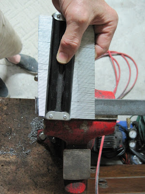

All of the drive components must be keyed to the axles. Almost everything is 1/4" key way. This can be a fight trying to get the key to fit in the component and the key way and still be able to slide in place. I found some key stock at Graingers that is undersized by two thousands of an inch. That is not much but it sure makes it a lot easier to fit everything together. Below you can see that I have cut the key to length and placed inside the universal joint.

Whoever painted this axle also painted the key way. I have already sanded the paint off of the outside of the axle so it will slide through the axle bearings.

It is also necessary to remove any paint or debris from the key way itself. A flat file works just fine. Be careful not to file the threads!!
 Finding the correct length for the key on the wheel.

 It will be necessary to use the notcher once again for fitting the side bars to the rear roll bar for welding.
All of the drive components must be keyed to the axles. Almost everything is 1/4" key way. This can be a fight trying to get the key to fit in the component and the key way and still be able to slide in place. I found some key stock at Graingers that is undersized by two thousands of an inch. That is not much but it sure makes it a lot easier to fit everything together. Below you can see that I have cut the key to length and placed inside the universal joint.

Whoever painted this axle also painted the key way. I have already sanded the paint off of the outside of the axle so it will slide through the axle bearings.

It is also necessary to remove any paint or debris from the key way itself. A flat file works just fine. Be careful not to file the threads!!
 Finding the correct length for the key on the wheel.
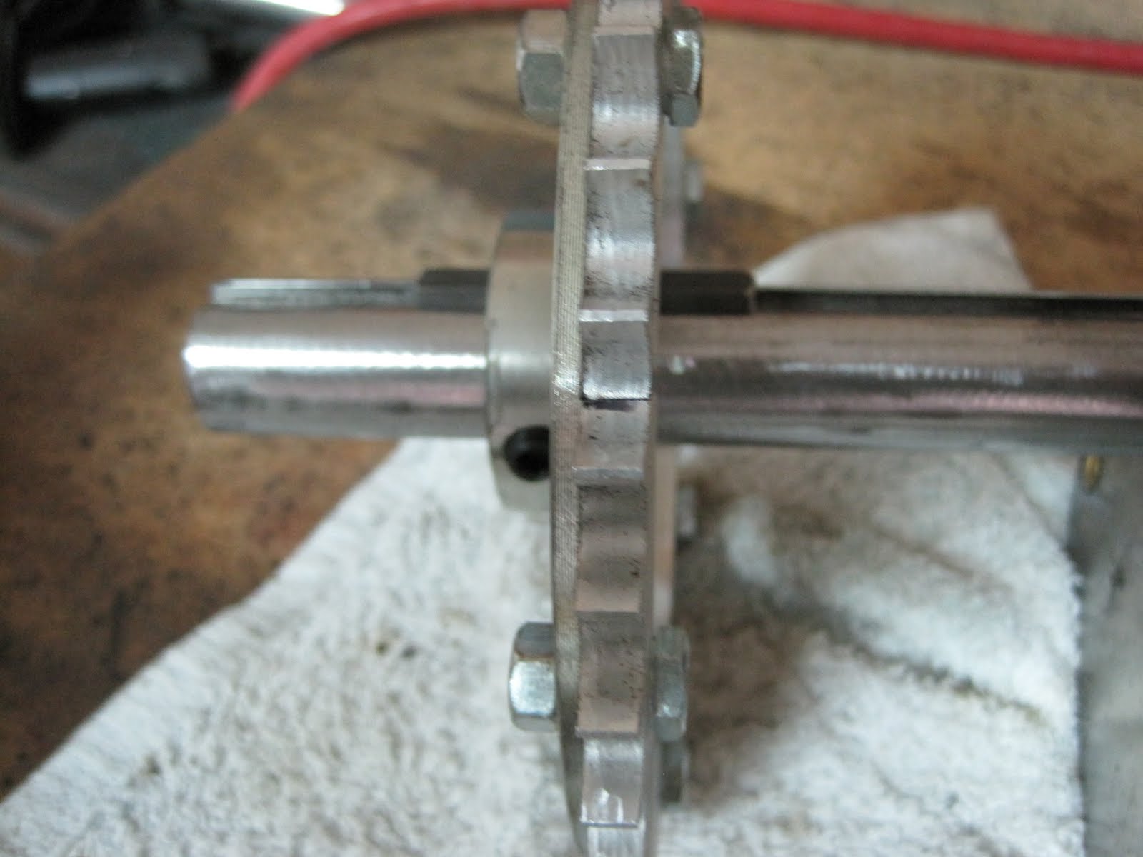
Keying the drive sprocket.
 Got these out of order.
 We will need landings for the forward legs of the roll bar. We want it to land about even with the front dash. I am using 1/4" x 1 1/2" angle iron because we want this to be good and strong. Once the roll bar is in place the frame will really begin to firm up.
 Using a plumb string to line the edge of the dash with the landings.

I want for the roll bar to be removable so we will need some landing mounts for the front landings. I have some 1" schedule 80 pipe that the 1" roll bar tube will fit inside of. This will give a little bit of wiggle room to adjust the roll bar legs before welding them into place. Then they can be drilled and bolted to the landings.
 Some of the following photos are out of sequence but they show the fab for the most important part of the cart. And what is the most important part of the cart. If you said the beverage holders you would be incorrect. That is the second most important. The most important part of course is the brake. The brake pedal is welded to a piece of 1" tubing that will pivot on a 20 mm Bolt. Why a metric bolt? That is what happens to fit snuggly inside the tubing.
The component parts ready for assembly.

 Moving along to the rear linkage of the brake I have decided to use those two extra 3/4" pillow block bearings that I have left over . This is a bit of overkill but hey, this is the brake we are talking about.

 Got these out of order.
 We will need landings for the forward legs of the roll bar. We want it to land about even with the front dash. I am using 1/4" x 1 1/2" angle iron because we want this to be good and strong. Once the roll bar is in place the frame will really begin to firm up.
 Using a plumb string to line the edge of the dash with the landings.
I want for the roll bar to be removable so we will need some landing mounts for the front landings. I have some 1" schedule 80 pipe that the 1" roll bar tube will fit inside of. This will give a little bit of wiggle room to adjust the roll bar legs before welding them into place. Then they can be drilled and bolted to the landings.
 Some of the following photos are out of sequence but they show the fab for the most important part of the cart. And what is the most important part of the cart. If you said the beverage holders you would be incorrect. That is the second most important. The most important part of course is the brake. The brake pedal is welded to a piece of 1" tubing that will pivot on a 20 mm Bolt. Why a metric bolt? That is what happens to fit snuggly inside the tubing.
The component parts ready for assembly.

 Moving along to the rear linkage of the brake I have decided to use those two extra 3/4" pillow block bearings that I have left over . This is a bit of overkill but hey, this is the brake we are talking about.
Subscribe to:
Comments (Atom)


