Tuesday, April 27, 2010

Now we can focus on the Top shock mounts. They are also referred to as "Shock Towers". As you can see in the next photo, the nearest point of connection for the top mount is the nose cone brace extending down from the firewall. I wish I could give some technical advice of why and how to make these mounts but I ain't got none. You want the shock to efficiently dampen the effects of bounce and droop that the roadway exerts on the front suspension. At what angle do we constrain the shock? How much preload? The answers to these questions as they pertain to a small go cart is probably that it matters little as long as both sides ride evenly. But I like to think of design and purpose in terms of what would work correctly in a real automobile. For now we will just try to get the shocks mounted as well as we can within the space we have to work with. You could fashion some kind of fancy shock tower off of the nose section if you like and that would also work. It will be a little tricky connecting a mount to the firewall brace because it comes in at an angle. That means that one side of the mount will be longer than the other.
In order to keep from cutting a special shape for the longer mount we can just weld a section onto one of the mounts as needed. An initial fit up shows that we need about 1/2" added to one of the mounts in order to keep them parallel with each other and also flat against the brace. After welding the pieces together just get out the angle grinder with a flap disc and grind off the extra weld.

What is preloading? Um, something you do before you go hunting. Good answer but not for preloading the shocks. Basically we are trying to anticipate a little bit of the droop we will get when the full weight of the cart is resting on the shocks. This would be a good time to talk about sprung and unsprung weight but we ain't. Just Google it if intersted and get ready for a good nights sleep. The highly technical way to preload a shock is to get a piece of square tube large enough to drill holes the same size as those in the eyes of the shocks. In our case we will use a piece of 3/4" square tube. Holes are drilled at a distance that is 1/2" shorter than the distance between the holes on the shocks. We will use this as a jig to locate the correct spacing for the upper shock mounts.We will start with the passanger side. It is a little more difficult to use the magnets to hold the mounts in place on the angled brace. These types of magnets are designed to fit flat against a surface but we are trying to hold the mounts at an angle. I will not say this is easy to get it just right. Does anyone have some bailing wire left?
You will notice that I am keeping the level on the nose to see if we are still level after fiddling with the mounts. Did I remember to check it before tacking on the mounts? Of course not!

The 3/4" tube that we are using as a jig is not quite as wide as the shock. So I will just tack one of the mount brackets in place and then connect the shock along with the other bracket in order to tack it in perfect alignment. If you do it this way remember to disconnect the shock as soon as possible after tacking the mounts in place.
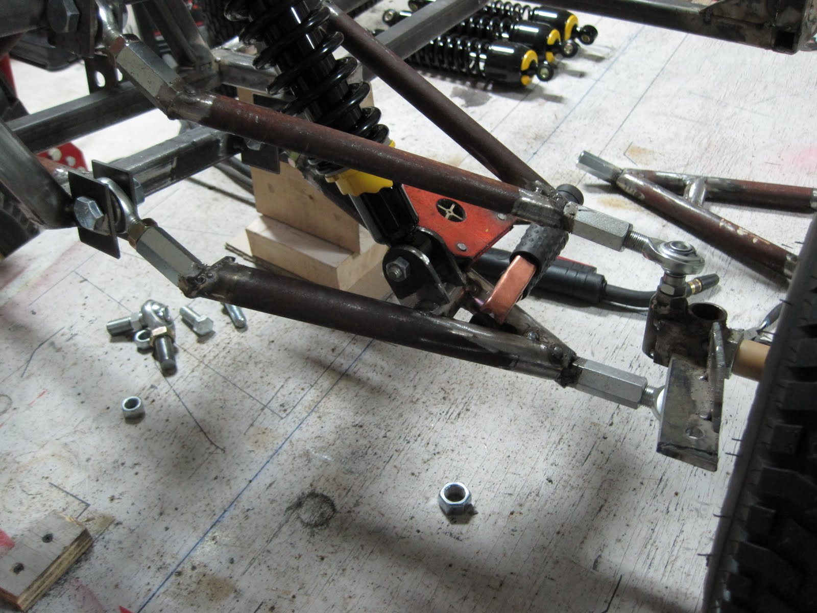
Let the welds cool before remounting the shocks.In this next photo it looks like the shock is rubbing against the brace but there is plenty of clearance.
Later on we will add a gusset to tie the mounts together as well as to the brace. You want these mounts to be as solid as possible. Now it is on to the drivers side to do it all again.

Friday, April 23, 2010

Our Shocks will not do us any good without a means to accurately locate them securely in place on the front suspension. How can we do this? If you said, first check to see if you have any bailing wire, I would say, "close but no hand grenade". We need some Shock Mounts. The bottom shock mounts will be welded onto the round tubes of the lower control arms. At this point goodness only knows where the top mounts will be connected so we will start with the bottom mounts and see where it leads us. But first we need a cross brace to connect the shock mounts to. We will be using the same 1" round tube that the control arms are made from. So how do we fit the flat end of a pipe to the round contour of the outside of another pipe? Sounds like someone is going to get to do some fancy grinding. But wait. Look what I found at the hardware store. It is a bi Metal hole saw that can easily cut contours in pipe or flat sheet. But how do we hold the pipe firmly and at the correct angle while it is being cut?


Now don't get me wrong, you can grind perfectly good contours in metal using a simple bench grinder and hand file. I do it all the time. But the following machine can make it all go a lot quicker and efficiently. It is called a Hole Saw Notcher. It's not your everyday notcher. It's a Model HSN-500 made by Pro Tools.


It can be used as I have it set up in a vice using an ordinary hand drill or you can mount it on a drill press which is probably the preferred method. But I don't have a drill press yet so we will make do with the vice and hand drill.

The good thing about this notcher is that it will hold the pipe firmly in place and at the correct angle.The saw cuts a "fish mouth" contour that fits snug between the straight and angled tubes of the control arm. One cut is a 90 degree cut and the other end is an angled cut. I was not sure what the angle needed to be so I did a practice cut first and adjusted from there. The ideal way to use a hole saw is to run coolant on it while cutting. When you don't have a coolant pump set up then the next best thing is to use a spray can of some kind of lubricant like WD 40 or Trilube and give it a squirt every once in a while in order to lower heat and friction. It is a bit messy but it will greatly aid in cutting as well as extend the life of the hole saw. This is not a very good photo but at least you can see the "fish mouth" contour of the cut. ( Hey I heard you say none of the photos are very good.) It fits nicely between the legs of the control arms. Did I get it to fit on the first try? Not hardly.Now that the brace is tacked in place we can move on to the shock mounts. The shock will be held by a mount on either side of the connecting hole. It is best to drill the holes in both mounts at the same time. This way the pieces can be bolted together and any grinding work will be the same. It is not that hard to set up using a C clamp if you take a little time and drill slowly. I am using the drill press at work while it has some open time.The hole saw can also be used to cut a contour in a flat piece of metal. But I am going to free hand the mounts on the grinder and see how they come out. A set of C clamp vice grips is a good way to hold onto the mounts while grinding the contours on the bench grinder. I don't know if you have noticed but the parts tend to get a little too hot to handle after a little grinding even with a good pair of leather gloves. The mounts do not look perfect but they will be fine.
When I got the mounts home I had to grind a little more off of the corners so that the shocks could pivot freely. Just bolt them together and grind away.


I like to use the actual shock with the mounts bolted on in order to get the bottom mounts tacked in place. Great care must be taken to be sure that the rubber cushion in the shock connecting hole does not get too much heat. Just try to tack the mounts as quickly as possible and then immediately remove the shock from the mounts. Remember that at this point you are just tacking everything securely into place. There will be hours of finish welding to do later.


The bottom shock mount is completed. Now go do the same thing on the other side. Try to get the mounts on the other control arm in the same location and at the same angle. I forgot to tell you that it is a good idea to have the axle sitting at the correct ride height when you attach the mounts so they will be somewhat at the correct angle. A good way to do that is to just attach the wheel to the axle. You could also just prop it up with something. The main idea is to get both sides the same so that the front end wil be level with the earth.


Tuesday, April 20, 2010

I took the axle up to the shop so I could use the band saw which gives a straighter cut than the chop saw I have at home. This saw is used to cut metal up to 7" diameter on a daily basis. I have used it to cut compound angles for different projects I have worked on. I have also ruined a number of $50.00 blades trying to make the saw do something it was not designed for.
It also has a coolant pump that increases cutting efficiency and prolongs blade life. I love this saw. Now you can say you saw my saw.


Hey look at this! The shocks finally came in. They actually look pretty good. Of course they said the same thing about the Titanic. I tried to read up on shock performance and functionality. I couldn't believe all of the considerations in choosing the right shock. Quite frankly I was shocked. Not that it is any big deal for a small cart but when they start talking about suspension frequency and spring coil rate and static squash it makes my head hurt. I just want a shock for a hokey pokey little go cart. These shocks are rated at 110 lbs. per inch and the extended length is 12 3/4". It has 3" of travel and is oil filled and coil over style. It is 5 way adjustable and has a 3/8" diameter mounting hole. But mostly they cost $11.25 each. I think they will be fine.

Now that we have the shocks I would like to switch back to the front end. I am really beginning to feel the pressure of a June 1st deadline to have this cart finished. Before we start hanging the full weight of the wheels and arms on the nose section it is a good idea to brace the uprights with some gussets. There should be little or no flexing in the frame because it could counteract the orderly and controlled movement we have tried so hard to build into the suspension. I am a little nervous about finding out how close it all works compared to the design.


Once again the gussets do not have to be anything fancy but they need to fit flush with the edges of the frame. Also don't forget to grind the mill scale off of both surfaces to ensure a good weld.


According to the CAD drawing we need to be about 8 3/4" from the ground to the bottom of the frame. That means I need a quick way to prop up the frame in order to confirm the dimensions and figure out where to attach the shocks. We are in search of the Holy Grail here. Actually we are in search of the "Holly Rolling Chassis" or Rolling Chassis for short. More on that later.
Anyway we need a Prop and it must be a proper prop and we need it fast. I always keep some 2 x 4 around for things like this. Pieces can be easily cut and fastened securely together using wood screws.

It just so happened that the wood pieces put together like this came out to 8 1/2". I was able to use a couple of pieces of 1/8" chip board on the bottom to get it up to 8 3/4". The angle of this photo makes it look like the sections are curved but it is an optical conclusion. They are quite straight.

The props hold the frame firmly enough to add the weight of the arms and wheels.
This is the moment of truth for the front suspension. No I will not use that bad pun again. I am not in suspense. I am downright terrified. Brenda and I were talking the other day about being a worry wart. I told her she should be glad I am not one. She started laughing hysterically. I guess I fret too much about details sometimes. But just like you I want it to be right. This is where we either feel the elation of success and make that man noise thing or check to see if we need to pick up a new cut off blade for the angle grinder on the way home from work tomorrow and turn in for the night. Which will it be?


So far so good. I tried to screw in all of the connections evenly. Just by looking you can tell that we already have some negative camber dialed in. How can you tell? The top of the wheel is tilted toward the inside. This is a good thing but even if it was positive we could easily adjust it thanks to the fully adjustable design of the front suspension. I didn't take a picture from the side but we also have some positive caster at this point, also a good thing. Positive caster means the top ball joint is tilted toward the back of the cart. As long as it is not tilted too much it will aid in steering in a straight line. When I lift the wheel up it gains a little positive camber as planned. So let's go put the wheel on the Driver side and see what we have.


It is very close to the same as the passenger side. Also the distance from the ground to the bottom of the coupling nut on the lower control arm varies only 1/16" from the two sides. I am really glad to see it that close. Now comes the real test. You have noticed that there is not a great deal of room between the straight and angled legs of the control arms. How do I know there is enough room for the shocks to fit? How do I throw a baseball 98 MPH? I don't.

The shock can be held in place with magnets long enough to determine proper fit.
I know the shock is a tight fit but I think we just might pull this off.

Sunday, April 18, 2010

Now I want to get the rear drive system a little farther along. There are a few considerations to uh uh consider when setting up the drive on any vehicle. First of all we need to think about the weight of the vehicle. The drive components for a small cart would not be adequate for a Baja racer. Employment of a 1" diameter solid steel axle with a 1/4" key way will be sufficient for our cart. I bought a 1"axle that is 44" long with a step down to 3/4" with a 3/4" male thread that will bolt onto the rear hub. You can see in the next photo how the axle has a step that will bottom against the inside of the wheel hub and allow the threads to stick out far enough to screw on a retaining nut. The wheel hub also has a set screw that can be tightened to secure the key stock that will be inserted in the key way. You could just weld the hub on if you like but you sure would have a hard time changing it out if you need to for some reason.
In the next photo you can see that the threaded end of the shaft is ready to receive the retaining nut. This is another good place to use a nyloc retaining nut because we don't need a lot of bolting torque. It just needs to stay in place.


We need to remember that this cart is set up with rear swing arms that will be flexing up and down. If we were using a straight solid axle it would not be necessary to account for any flexing. But then every bump in the road would try to jar your brains out. So how do we still use a solid drive shaft while compensating for the axial movement? If you said just use some bailing wire I would say close but no cigar. If you said how about using a 1" universal joint then I would say Bingo! A flexible universal joint or U joint is an amazing invention designed to transfer power where there is any offset between the source of power and point of transfer. In our case we will be transferring power from the drive sprocket in the center of the cart to the rear wheels via a flexible universal joint and a section of solid axle. You could also use a Constant Velocity joint. What the heck is that? That is commonly referred to as a CV joint and is used extensively in front wheel drive autos as well as other applications. I have never used a CV joint before but it is something I need to learn to mess with. Maybe next project. I don't know very much about U joints either but it will be well suited for this application. I bought brand new U joints and they are not cheap. Next time I will shop around on E bay and find a deal.


The next picture shows the U joint fitted to the center sprocket jackshaft. The trick now is to determine how long the axle needs to be so it can be cut to the correct length. The axle I bought is a solid axle that is threaded on each end. It is just a matter of cutting the correct length off of each end. My hope was to have enough left in between the ends to use for the center jack shaft that will drive the sprocket. I think my luck is going to run short. About 1 1/2" short to be exact.


I will use a very sophisticated approach to determine the final cut length of the axle. It employs the use of aerial surveying techniques. Simply place the axle with the wheel attached at the proper spot under the U joint and the Azusa flange on the swing arm. Set the wheel at the desired track width. You will recall that wheel base refers to the distance between wheel centers from front to back. Track refers to what? If you said distance between centers from side to side then we need to give you a cigar. The track on the font wheels is somewhere between 55 and 56" so we will shoot for the same on the rear. You need to bear in mind that the drive shaft will need to be free to float in and out of the U joint to compensate for the movement up and down of the swing arm. I figure about 1/4" will be enough.


One final check before completing the precision measurement. Yep looks about right. Actually I did use a tape to measure the distance to the hub. The axle fits into the hub 4 1/8". I hope I don't forget to add that to the overall length of the axle. I think I will go write it down right now.

Friday, April 16, 2010

Now that the nose is tacked into place we can begin building the bracing and shock towers for the front suspension. You will recall that the floor frame is made with 1" square tube with a 1/8" wall thickness. We will be using 1" and 3/4" square tube with a 1/16" wall thickness for the rest of the framing. I had already installed the framing for the front firewall some time ago just to make it look like I was doing something. It is very easy to become discouraged when building any project. Sometimes when I get tired at night after working on the cart I feel like I'm not getting anywhere and just want to give it up. It took me two hours just to get these two front nose braces cut and in place. The point is that it is OK to use psychology on yourself. I know a carpenter that can frame a house in record time but don't expect the finish work to ever be completely done. He loves to see progress and that is what drives him. That is OK. Tedious and time consuming tasks are often the most important in terms of assuring everything fits and works together properly but it is often hard to tell visually that anything was accomplished. So go ahead and bolt on a seat or stick the steering wheel in place as long as it will not interfere with the rest of the construction. The idea is to show progress and begin to get a feeling of accomplishment. This next photo shows a little more clealy the front nose brace ready to tack in place. These braces fit at an angle. This requires cutting compound angles in order to get the braces to fit flush with the pick up points. I employ a highly sophisticated method to determine these compound angles. I use a special tool for measuring the angles. The technical term for the device is an angle measurin thang. If that doesn't work then I put a piece of metal tube between the pick up points and hold my mouth just right and make a precision looking mark with a magic marker then walk over to the vise, insert the tube at an angle and get out the hack saw. Then I go to work with the bench grinder which will have to work some overtime.
That should hold the nose firmly in place so we can continue the fit up of the front suspension. That will primarily consist of fitting up the rack and pinion steering and placement of the shock mounts. I have the shocks on order but they have not come in yet. I found some at a fairly decent price. I hope the quality is good.


Wednesday, April 14, 2010

Now that I am through wasting time let's see if we can figure out where to put the rear swing arms. It is important for the axles to be perpendicular to the center line of the cart. There is more than one way to do this but I like to pick out a main frame cross member and use it as a reference point. You simply measure the same distance to both sides of the mounts.

I am able to use a solid metal ruler for the final measurement. We also want to be sure that the mounts are centered across the frame. In other words you don't want one axle to be longer than the other or in layman's terms one wheel done sticks out further than the other. It is also wise to be sure that the center line of the axle is located at the correct location. ( That sounded stupid) This will determine the wheel base which means what? If you said the distance between the front and rear wheels you would be correct. Did I pay close attention to this? Let's just say that our wheel base is going to be a couple of inches longer than originally planned.

But at least the square confirms that we are perpendicular to the center line as determined from measuring evenly from the frame cross member. The next photo shows the square lining up with the edge of the mounts and the edge of the frame. You may ask, Why not just use the square and forget about that measuring stuff? That works for me but it is sort of like one measurement validating another. In this case I was pleased to find that the mounts were square with the frame after spacing the sides of the mounts equally from the frame cross member. Now let's suppose that the square did not line up with the edge of the frame after equally spacing from the cross member. Has this ever happened to me? (The armadillos are piling up) At this point you have to decide which dimension you trust more. Or, how about just splitting the difference. I like for the dimensions to be perfect but that seldom happens. Just remember that the idea is to head straight down the road.


It is always best to clamp the parts together before welding but in this case it would lift the frame unevenly off of the table. I am using the biggest magnets I have to hold everything in place. Magnets are a marvel to me. They are almost magical. Can anyone really explain how a magnet works?


Now that we have the mounts tacked in place it is time to get the Azusa bearing mounts in place. You want to attach them flush with the inside of the frame rails and bolt the bearings on the outside of the mounts. Once they are tacked in place we need to back them up with a support gusset to be sure they do not move. This next photo shows a support gusset for the bearing mount and ready to tack in place. Remember that we are still only tack welding things in place in case we have to move something. Will I be tacking anything else in the wrong place before we are through? (One little two little three little armadillos)


You can see the gusset tacked in place in the next photo. Remember that the frame is turned upside down. I mention this just as a frame of reference. It is easy to get parts in the wrong place if you forget. We will need gussets on both sides of the mounts. These gussets will not be noticed but they will be doing a lot of work. Give them your best welding effort.


We will now turn our attention to the front nose section. It has been sitting up there at the front wondering when it will get attached to the rest of the frame. It will be tilted upwards at an 8 degree angle. This should give us the propper caster angle. I made some chipboard wedges to help position the nose at the correct angle but they didn't work very well. I am just using them to prop up the front with a metal ruler under it to give it a little more lift. The level will tell us when the nose is level. Level with what you may ask. Why, level with the earth of course. If it is not level with the earth then it is easier to change the position of the nose than it is to change the level of the earth. And no it does not matter how many elephants you heard onto the southern tip of Africa it will not cause the earth to tilt.

This is not a very good photo but it shows that the bubble is between the hash marks on the level so that is a good thing. We may not be level with the rest of the cart but we will be level with the earth.


I will now hold my breath and tack the nose into place. Or I could hold my nose and tack the nose into place.