Monday, September 27, 2010

This morning when I turned on the water in the shower somehow I lost my balance for a second and knocked the heel of my foot against the bottom of the shower door. There is a plastic strip that holds the seal in place on the bottom of the door and it has a sharp corner on it. So first thing "I cut my heel and had to cruise on back home". ( Name that tune) I find it interesting how so many little mishaps seem to be always waiting for just the right time to occur. I was using one of the magnets to hold the roll bar in place temporarily until it could be positioned for tacking into place. Those magnets are made for sticking to flat surfaces but not to round bars. So you can see the magnet down there that let go from its' perch on the top of the roll bar. And just where did it choose to land? Yes, right on top of the gas tank. And did it choose to land flat? No way! It landed square on the corner in order to make the deepest dent possible. You can see the proud smile on that magnets face.
I have been fighting with the roll bar trying to get it even as viewed from the side and the front. I now realize that the following photo should have been shot using the zoom. I was trying to show what the roll bars look like from the front view. They are not perfect but they are as close as I am going to get them.


Side view of roll bars.


Here is a quick list of the fabs that need to be finished.
1. Roll bars
2. Brake caliper
3. Break linkage.
4. Engine mount.
5. Finish keying axles.
6. Install hydraulic tank.
7. Hose and piping
8. Body mouldings.
9. Floor board and dash.
I know that sounds like a lot but fortunately I am already in various stages of working on most of it. I decided to mount the engine on some 1/4" angle iron. We will not need to allow for any kind of adjustment in the engine mount because it is not attached to any drive train as in a regular friction clutch application. There just needs to be adequate room for the hydraulic pump to be mounted to the engine. It will be a tight fit in places but so far it appears that everything can be located without any major changes of anything that has already been mounted. Here is the engine mount ready to be drilled with the engine mounting holes.


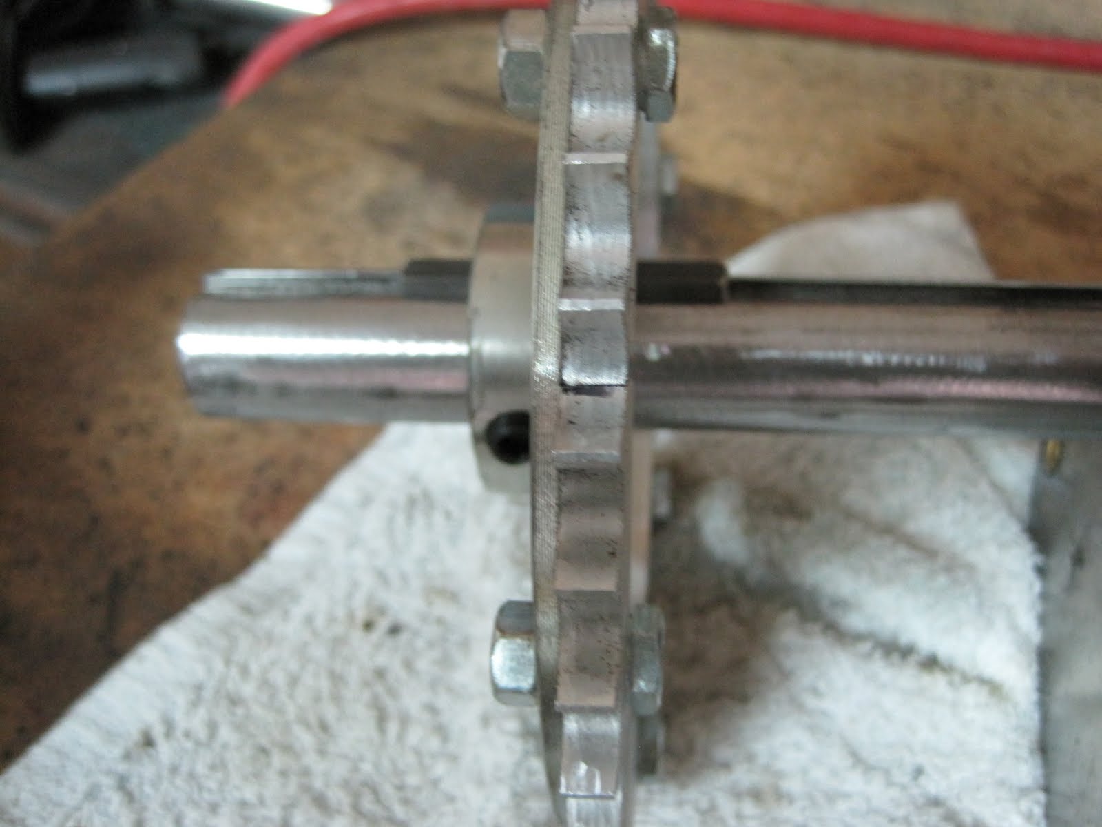
The brake caliper proved to be a tight fit but I think it will work just fine. I will mention at this time that the brake disc is not mounted in the best place possible due to room constraints. It is mounted on the primary drive sprocket axle. The better location would be the secondary driven sprocket axle. Why would that be a better choice? If you said because now the braking depends on the integrity of the chain, you would be correct. In other words since the braking power, just like the driving power, is transferred to the rear sprocket via the chain, the braking power as well as the driving power will be lost in the event of a broken chain. I thought long and hard about this but this brings up another issue. There is not quite as much ground clearance as I would like to have on the rear sprocket because it actually protrudes from the bottom of the frame an inch or so. I will try to build a skid plate to help protect it. The brake disc has a larger diameter than the sprocket so it would protrude even farther making it vulnerable to getting bent on a rock or something solid on the terrain. Bent brake discs don't work either. You may suggest that the brake disc could be mounted on one of the outboard drive axles. That could also work but then it would be necessary to build the caliper mount as part of the swing axle so it could float as the axle travels up and down. We could go on and on but a decision has to be made. I have opted to keep the disc up out of harms way and trust the integrity of the chain. After all it's not like the cart may go sailing through an intersection if the chain fails.


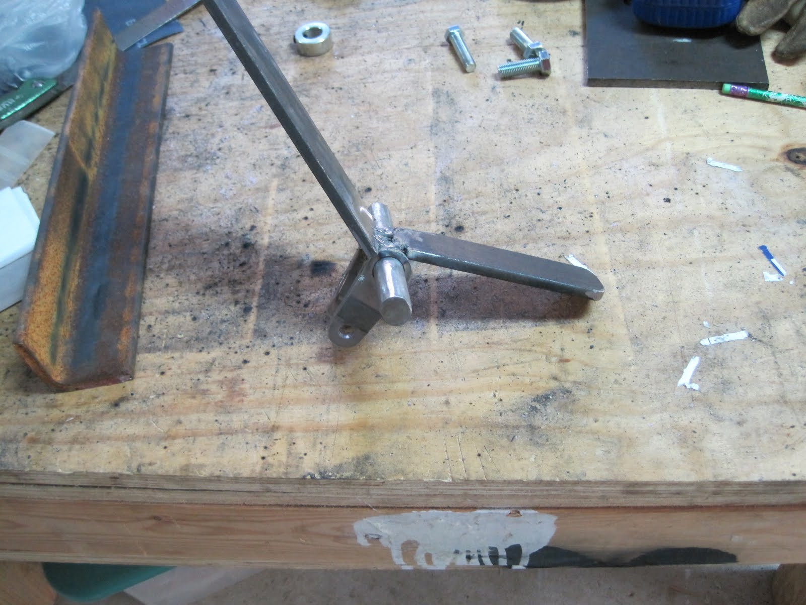
A piece of 1/8" angle iron will be adequate for the caliper mount.


The caliper is designed to float back and forth on the mount as needed to line up with the disc. The lever will be connected to the control rod. In the following photo you can see how the channel in the mount fits into the slot on the caliper. Now the control rod can be attached.

Wednesday, September 22, 2010

I am finding that the space for the chain tensioner is very tight. When I cut the chain to the correct length I found it to be about a half link shorter than I would like. So what should I do? If you said just get the come- a -long and stretch it that probably wouldn't work too well. Fortunately they make half links for this purpose. Just add it next to the master link and you are ready to go.
At this point in the project I am working on several things at the same time to keep things moving along. There are some fabs that cannot be completed until another component part is assembled and in place. For instance, I am not sure if the brake caliper will fit where I want it until the brake linkage is in place. The brake linkage is off set and therefore requires an extra shaft. So I have been busy working on a lot of things that need to be done before finalizing the designs of mating parts. I have been bending the side arms of the roll bar. It will be necessary to use the notcher once again for fitting the side bars to the rear roll bar for welding.


All of the drive components must be keyed to the axles. Almost everything is 1/4" key way. This can be a fight trying to get the key to fit in the component and the key way and still be able to slide in place. I found some key stock at Graingers that is undersized by two thousands of an inch. That is not much but it sure makes it a lot easier to fit everything together. Below you can see that I have cut the key to length and placed inside the universal joint.


Whoever painted this axle also painted the key way. I have already sanded the paint off of the outside of the axle so it will slide through the axle bearings.


It is also necessary to remove any paint or debris from the key way itself. A flat file works just fine. Be careful not to file the threads!!
Finding the correct length for the key on the wheel.


Keying the drive sprocket.
Got these out of order.

We will need landings for the forward legs of the roll bar. We want it to land about even with the front dash. I am using 1/4" x 1 1/2" angle iron because we want this to be good and strong. Once the roll bar is in place the frame will really begin to firm up.

Using a plumb string to line the edge of the dash with the landings.


I want for the roll bar to be removable so we will need some landing mounts for the front landings. I have some 1" schedule 80 pipe that the 1" roll bar tube will fit inside of. This will give a little bit of wiggle room to adjust the roll bar legs before welding them into place. Then they can be drilled and bolted to the landings.
Some of the following photos are out of sequence but they show the fab for the most important part of the cart. And what is the most important part of the cart. If you said the beverage holders you would be incorrect. That is the second most important. The most important part of course is the brake. The brake pedal is welded to a piece of 1" tubing that will pivot on a 20 mm Bolt. Why a metric bolt? That is what happens to fit snuggly inside the tubing.
The component parts ready for assembly.


Moving along to the rear linkage of the brake I have decided to use those two extra 3/4" pillow block bearings that I have left over . This is a bit of overkill but hey, this is the brake we are talking about.


Friday, September 17, 2010

I have gotten behind in my housekeeping again. It is time to vacuum all of this metal grind and clean up in general.

There. That's better.
I have been working on a number of different things at the same time trying to keep the project moving. Some things must be completely fitted before another related item can be properly sized. For instance I need to be sure that the brake disc is positioned so that the caliper can be accessed by a control cable. I need supports for the front roll bar landings that will work in with the contours of the body. So the following are a few miscellaneous things that I am doing so we can get serious about finishing this cart.
I needed to get an idea of how the chain was going to fit and work with the chain tensioner. In case you have not worked with roller chain before I wanted to show a procedure for breaking the chain and reassembling it. They make some fancy tools to make this easier but the method I use is really not that difficult. I am sure there are better ways to do this but this works for me. First of all you need to determine how long the chain needs to be. The easiest way to do this is to test fit it to the sprockets. You want to start out with as much adjustment as possible so that you don't run out of room to adjust the chain before the chain wears out. My experience with chain dates back to the 70's when I had a little Yamaha street bike. My son Cory tells me that chains are much better today than they were back then.
Once you have determined how long the chain needs to be you will need to break it. It is not so much breaking it as grinding it. If you are careful you can actually use the bench grinder to grind off the outside of the posts of the link.


Once the end is ground off then you can use a metal punch that is slightly smaller than the diameter of the post and drive the post out of the link. This actually takes more force than you might think. I like to drive it against the wood of the top of the work bench because it allows the opposite end of the post to sink into the softer wood as it is driven out. It will most likely not budge for several strikes. You can see that it is starting to move in the next Photo. I probably hit it with half a dozen solid blows before it started moving.


Next you can lightly clamp the chain in the vise and finish driving through the leg if need be. Then just repeat the procedure on the other leg of the link.


The link can now be completely removed from the chain.


The chain can now be reassembled using a master link.


I have also been working on the test fiberglass hood. I am just experimenting with some different ideas of how to contour the body panels. The surface of the foam mold has to be properly treated before the fiberglass is applied in order to be sure the fiberglass does not stick to the mold. First of all the mold needs to be completely covered with plastic boxing tape. And I mean completely covered because I left a very small strip uncovered and it stuck to the mold very aggressively.


I am leaving one edge untapered to see if that works better.


The last step is to wax the surface as an added deterrent to sticking. I just used a bar of paraffin to scrape on the surface.

There is quite a bit to the actual application of the glass and epoxy resin that I will cover later. Here is the test part with one coat of glass and resin. This will be interesting but not easy.

I have been trying to get a visual idea of how the finished cart is going to look. Templates of the side panels are attached in the following photos.

Sunday, September 12, 2010

Now this is more like it. The roll bar is now made in one piece and it is straight in both planes. It is not perfect but I learned some of the tricks of bending pipe. Like I said before the only way to learn how to bend pipe is to do it.

I finally saved enough money to buy the engine I wanted. It is a Honda GX160. It has a 160 cc cylinder and is rated somewhere around 5 horse power. Now this is the top of the line commercial grade engine. It is the same engine you will find on rental equipment. You can buy an off brand engine for less than half the price and that would work fine. But this Honda engine is built much sturdier and will start every time you pull the rope. It is certainly not necessary to buy a new engine either but you stand the chance of getting a used engine that needs repairs if you go that route.

I knew that it was going to be a tight fit in the engine bay but it looks like I can make this work.


You can see in the next photo that I will have to shorten the jack shaft in order to move the engine over far enough to get it inside the engine bay. I had planned to mount the brake disc on the outside of the drive sprocket frame. I have placed the brake disc inside the frame next to the drive sprocket and it looks like there will be enough room for the brake disc, drive sprocket and idler sprocket. It looks like I will be able to mount the brake caliper from the top of the frame.


Friday, September 10, 2010

Well well well sometimes it just does not turn out the way you think it will. The rear roll bar looks fine when viewed from the rear but looking at it from the side is a different horse color. It is the color of a very crooked horse. I was not paying attention to maintaining squareness in both planes. I think the problem developed when I welded the two halves of the roll bar together while it was sitting in place on the cart. I should have taken it off of the cart and placed it flat on the floor to weld it together. This next photo is not very clear because it is so humid out here tonight. I brought the camera out here to the garage from the air conditioned house and the lens fogged up. You can see that the bar is nowhere near straight. So how do I correct this? I have tried to put it back in the bender to straighten it out but it will not fit far enough because this is a different plane that I need to adjust. The more I try to adjust it the worse it gets. It's not that the roll bar wouldn't work perfectly fine like this but I just can't stand how bad it looks. I'm sure there is a way to straighten this out but I just don't know what it is and don't have time to try and figure it out. I have no choice but to start over. Luckily I have enough pipe left. I think I am feeling a little depressed because I thought I was making headway. I noticed that next month will be a year since I started the plans for this project. I should have been through by now. So I will do what I usually do when I find myself in this situation. And what is that? Did you say go inside and eat a box of Twinkies? No, I will call it a night and go dream about pipes. Next I will attempt to bend it all in one piece like I should have in the first place.

Tuesday, September 7, 2010

There is a very simple way to reverse the rotation of the pedal assembly by adding another pedal that can be pushed in the opposite direction. It does not need to be quite as long as the forward pedal because reverse will not be used all that often. The only effect of making it shorter is that it is a little harder to depress because of the reduced leverage. But I want to keep it as short as possible simply to keep it out of the way of the floor board. After determining the length of the pedal we need to weld it on to the pivot shaft at an angle that would be convenient to step on and rotate the shaft in the opposite direction.
With this set up the forward motion will be activated by pushing the top pedal forward and the reverse is activated by pushing the bottom pedal downward which in turn reverses the direction of the valve spool.

Now we need to move on to fabricating the roll cage. I do not anticipate a real need for a roll cage on this cart as it will move relatively slowly and should have a fairly low center of gravity and a wide wheel base. But I do want it to be as safe as possible and you never know what unanticipated stunts that kids may pull. The roll cage is made from 1" diameter tube. This means it is 1" outside diameter with a wall thickness of a little less than 1/8" thickness. It will be strong enough for a roll over if we use just a little bit of planning. We will need to revisit the pipe bender for this Fab.


As a quick review it consists of a hydraulic jack that is pumped manually with a handle.


The pressure is released by means of a twist valve that is located at the bottom of the jack.

The top rollers can be easily removed in order to insert the pipe if needed as well as modify the bend radius.
I would be lying if I told you I was an expert at bending pipe. I can tell you right now that it is just as much an art as it is an exact science. All I can really do is give a few pointers but you really have to actually bend some pipe in order to learn. We will start with the back of the roll cage. For time and simplicity sake I have opted to make the rear roll bar in 2 pieces. It is always best to make the sections of the roll bar in one piece if possible especially if it will be used as a racing cart. I have made a chipboard template for a pattern to follow. The radius of the one inch bending die that is supplied with this bender will make a six inch radius if you bend the pipe 90 degrees. The radius I am trying to achieve is larger than six inches. What this means is that it will not be possible to make the desired radius by simply putting the pipe in the bender and bending to a 90 degree angle that is required. It will be necessary to bend a little bit and then loosen the bender and move the pipe a little farther and bend some more. I know this probably doesn't make a lot of sense but you have to start somewhere.
The first thing you want to do is be sure that your piece of pipe is long enough to make the desired part. I just leave a few extra inches to be sure. You will be able to leave less of a cushion as you get a feel for how the bending works.

I went ahead and bent the first piece and as you can tell my radius ended up a little smaller than the template. This is no problem because I chose the radius of the template more for its visual appeal than for any form or function. Now that I have one side done I will use it as the template for the other side in order to assure that they are the same. You can begin to understand why I wanted to make this in 2 pieces so that I can just cut the sections to length. In other words that is most likely what I would have to do anyway because my skill level is not great enough to start the second bend at the correct spot.


As a little hint it is helpful to mark the next piece at the center of the radius of the piece you are trying to duplicate. You can seen the black mark on the straight piece in the next photo. If you place this mark in the center of the radius of the bending die then you should be able to start the bend very close to where you want tit. I'm sorry about that extra t.
It is necessary to bend a little at a time and remove the pipe to compare it to the template and continue to bend the radius accordingly.


Just a little bit more. I love this!!
It would be easy to simply weld the back portion of the roll cage directly to the frame but I want to build in some adjustment. I had a couple of pieces of one inch schedule 40 pipe that can be used as a base and the one inch tube will fit inside. They are welded onto the frame and then the adjustment holes can be drilled through both pieces once the roll bar is inserted.

We need to be sure that these mounts are welded on straight.After having Miss Paige sit in the cart I discovered that the roll bar is not quite as high as I would like it to be. So now I need to add a short length to one of the pieces. The easiest way to weld pipe together is to clamp both pieces in a piece of angle iron.

This is the end that will fit into the mount on the frame. The flap disc on the angle grinder will sand off the excess weld so it will fit into the mount.

Now we can cut the other half of the roll bar to the same length as the first one.


With both halves of the roll bar inserted into the mounts we can now cut the other ends to the correct length.


You can tell from the next photo that the ends do not line up. What are we going to do about that? If you said bang on it with a sledge hammer then we don't need to get that drastic, yet. As you can see the half on the left is level so all we need to do is remove the right half and make a little visit to the pipe bender.


There. Now that was much easier than the hammer idea and not nearly as noisy.


As I said earlier I don't really like to make a joint in a roll bar so I will just have to make it as strong as possible. In this case we will slide a section of 3/4" tube inside of the roll bar and weld it to both halves. Then we will slide a 1" locking collar over that joint and weld it all together. Be sure and slide the 1" collar on before welding the 3/4" tube to both sides.


The following photo is blurred but it shows the two halves welded to the 3/4" tube. The collar can be slid over the joint after the excess weld is ground off.
That hole in the collar is for a set screw if you are using it as a spacer or perhaps to hold a piece of key stock in place. We will not need to use the set screw since it will be welded in place.The rear section of the roll bar is in place.